How to choose/make your ergonomic keyboard
In my last article, I explained why keyboards as we know them are hurtful for our wrists. Here, I’ll build on that to explain what to look for in an ergonomic keyboard, and how I built my own.
What to look for
Essentially, each design feature of ergonomic keyboards aims to solve the issues I discussed last time.
Layout
The QWERTY layout is suboptimal, and doesn’t give access to the most frequent keys in the best of places.
I personnally didn’t go on that route, as I feel like having the same layout as the majority of people is more important to me than this last bit of optimization. I get that other ergonomics enthousiasts would go the extra mile though.
Size and form factor
The first biggest decision you have to make when choosing your keyboard is probably the form factor. Depending on where you’ll use it, If you’ll travel with it, and how much you feel ready to learn new ways to type, you’ll want to go with different sizes and number of keys.
For example, you can have a very slim and portable keyboard, but it will feel less thocky and cosy to type on, similarly to a laptop keyboard.
You can also choose a model with less rows and/or columns implying smaller footprint on the desk and better portablility. The drawback is having to find creative ways to keep all of the functionality while missing some keys.
Depending on what you want to maximize, you will sacrifice something else.
Concavity
If we look at our hands from the top, finger movement goes in straight lines. But if you look from the side, It’s actually a curve with the second finger joint as a pivot point. I never tried it myself, but I will probably try that for my second ergonomic keyboard because it looks like it feels amazing. The only drawback I see with that is the bigger total height, and higher manufacturing complexity.
Wired or wireless
Pretty self explanatory, wireless is cleaner, easier to travel with. But for that to happen you need batteries, so you have to keep it charged, and will have higher ecological impact.
Firmware and software
This is easy enough, there are three main options:
-
QMK
The more common one for wired keyboards, you can customize your layout and various other peripherals, then flash the firmware on your board.
-
ZMK
Similar to QMK, but more suited for wireless keyboards.
-
a random proprietary other one
This one you should avoid in my opinion, because the other are open source but so good that many keyboard manufacturers use them anyway. You can do almost anything with them, whereas you’re not sure with other proprietary ones.
The firmware is a really important part of the keyboard, especially if you choose models with fewer keys. It’s what allows you to customize everything to your liking, and to what suits your use cases the best. I will probably write a more in-depth article to detail my firmware configuration process with QMK.
The current market
Now that we know roughly what we want and what we don’t, what are the options?
Disclaimer, I’m not affiliated with any of these, I just use them as examples for what’s available to buy. (Mine is cooler anyway because I made it 😏)
Here’s what the common solutions looks like:
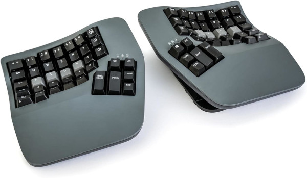 This one is a Kinesis Advantage 360. It seems to be the preferred bought one of many people, including ones with big enough audiences that you propably heard about it before. It doesn’t look super easy to travel with, but for an everyday home setup it has every comfort and ergononic feature I discussed above. The only issue can be the price.
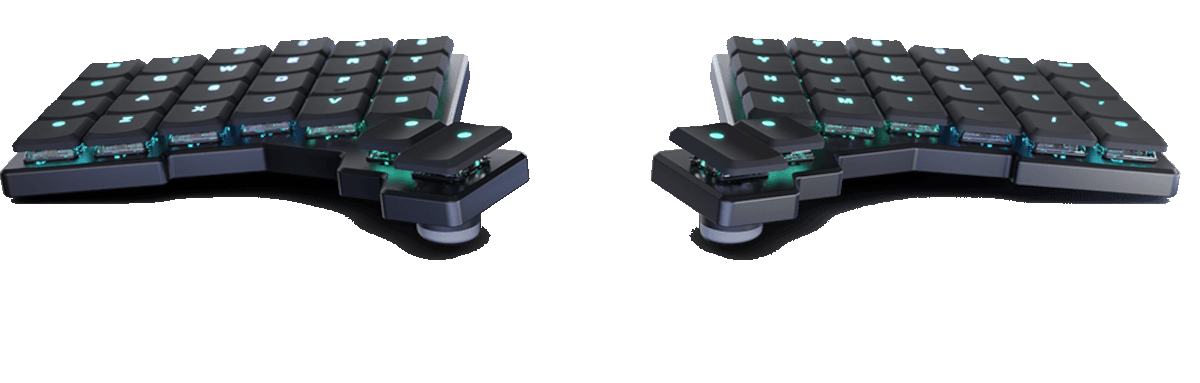 Another option that’s more on the extremely portable side is the Voyager, from ZSA. It uses QMK, and is 16mm thick (burger people, here is your cue to make a quick search and learn the superior system). Stylish, portable, but still expensive…
I showed the two ends of the spectrum with those examples, you can go have fun looking for what exists out there for yourself. Note that open source and open hardware models are good enough that you can buy an already manufactured one, for 3 times the price of making it yourself.
DIY route
TODO - Reframe as a telling my own process rather to giving general advice
I’m always in favor of learning new stuff, especially when it saves a buck or two, so here we go:
Choosing a project
The obvious first step. You will take what’s discussed above in consideration, because the project has to get as close as possible of your ergonomic criteras and use case. The other additionnal question to ask yourself is about what you’re ready to do/learn manufacture-wise. Do you want to learn soldering? Do you already own a 3D Printer? Will you buy the keycaps or print them yourself? With or without the labels? When going the DIY route, every challenge will be yours to overcome.
Ignorance is bliss and can get you into a project that is way harder than you envisioned. This is often beneficial, so I don’t want to discourage you! I’d say that there is a balance between not knowing what you’re getting into leading to giving up, and analysis paralysis.
Last point: A well documented and praised project is also a plus. An exhaustive and comprehensive bill of materials, a clear history of iterations and variants; anything that reduces guesswork will ease the whole process.
Sourcing
For electronic components like switches, diodes, microcontrollers, Aliexpress or Amazon are unfortunately the easiest and cheapest choices by far.
Keycaps are pretty expensive, even there. Depending on the project, you might need a certain number of different sizes which can force you to overbuy a bunch.
If you’re not handwiring, you’ll have to send gerber files to a Printed Circuit Board manufacturer and order it there. Same if you don’t own a 3D printer. Those platforms usually offer 3D Printing services as well.
Printing
Everything depends on your level of experience with 3D Printing, but if you’ve got your filament and printer decently dialed in, making the case parts won’t usually be a problem.
The keycaps however are another story. If you go Choc, I’ll guess it’s pretty easy to print because the details are not that tiny. But for MX, you better have a decent printer and dry filament, or you’re in for a ride (don’t ask how I know).
This project is single handedly the one that turned me into a believer of the impact of wet filament, and made me buy a dryer. The MX ’+’ shape was either making my prints blob and fail, had inflated dimensions that ended up gripping with the switch casing, or would just break on me the second I tried to insert the keycap on the stem.
I tried various models, orientations, MX female shapes, and I never suceeded until I made my own custom keycap and dried the hell out of my filament. The apparently most mundane part of the keyboard took the vast majority of my time for the project. I’m sure that the majority of the models I tried would have been okay with dry filament, but I only had one roll of purple (that came wet from the factory) so I never changed that part of the equation. I started doubting reality itself at some point, so make sure to channel my past pain into your upcoming success.
Soldering
I went with the handwiring route, the most artisanal of them all. If you’re buying PCBs you won’t have to do the majority of this section.
The first thing to do is probably to insert all of the switches in their slot.
Once you’ve done that, I would say there are two main parts to handwiring a keyboard:
- Matrix
- Diodes
- Rows
- Columms
- Connection to the board.
Matrix
Diodes
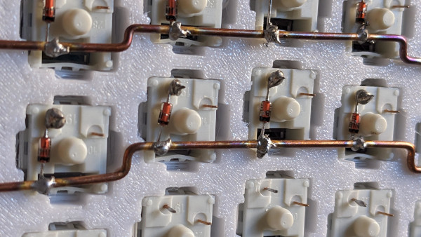
First, I soldered all the diodes to the switches. That’s easy, long, but also therapeutic. Simply identify the direction of the current, often displayed by an offset line on the diode. then, make a small loop on the leg, and repeat that for every diode.
When that is done
Rows
I used the copper rods method, which is explained by Joe Scotto in his handwiring guides. You find copper wire of decent diameter (make sure it’s the solid kind, and not stranded). Strip it of any insulation, then grip it in a vice of grab a friend with a pair of pliers. You cut a good portion of it, then grip it in a powerdrill or your own pair of pliers, and you twist it for a while to make it straight. When you have a few good lengths of straight copper wire, you can get to work.
For rows , I measured the distance between the first and last diode legs of the row, and cut some copper rod a bit longer than that length. Then I used my vice and small pliers to make 90° turns that match columnar offsets. I made sure it could attach to all of the diodes at once.
Finally, I got my iron hot and soldered the rod, left to right while holding it with a small pair of tweezers. You can use whatever you possess, just make your it’s not your had because copper is a really efficient heat transferring material.
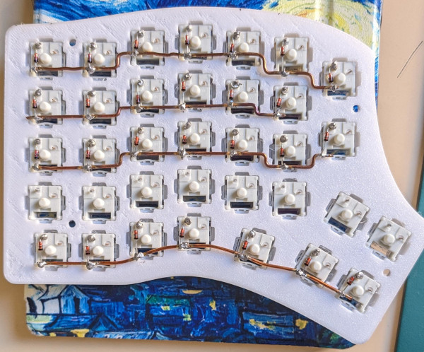
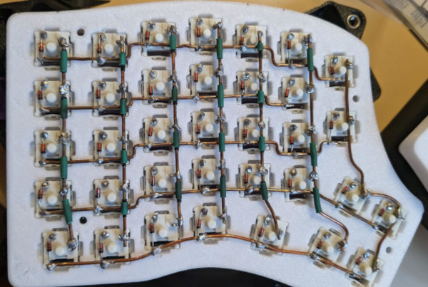
I repeated that for each row and it ended up looking like this:
Columns
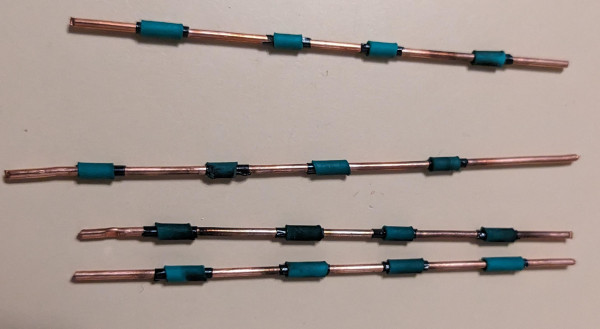
For the columns, I opted for small patches of insulation at the intersections with the rows. The insulation consists of a small loop of electrical tape, layered with part of a heat shrink tube. This is also tedious to do, but looks nicer and has this really artisanal feel to it that made the process pretty soothing.
The prepped columns look like this:
When all of the columns were ready, I used trimmed diode legs as crutches to tie them to the switches pins. I feel like that ensured solid electrical connections even though it wasn’t the fastest to do.
Connection to the board
Now equipped with two matriced halved of a keyboard, I went on to wire everything to the Arduinos. That was my first time following schematics, and I found it pretty straightforward because every pin was clearly marked on the microcontroller. Having a multimeter made everything easier as it allowed me to test continuity at all parts of the wiring process, troubleshooting errors earlier. For the TRRS Jack ports notably, that was really helpful. You can probably do it without one, but I feel like that’s equivalent to going in blind.
Firmware flashing
Now that everything is soldered it’s time to test the beast! I cloned the QMK repository, read a bit of documentation and went in to create my own layout. I tried QMK Configurator which worked well to visualize my future layout, but I couldn’t figure out how to make the exported config work though, so I hardcoded it myself in C files of the QMK repo while looking at the configurator for valid key references. After some trial and error, I managed to have my first working layout.